Noe’s Juke Box | Main components and schematics

Main parts

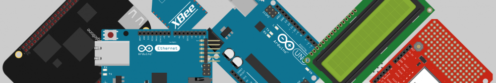
Juke Box showed here is based on the following main components :

components photo

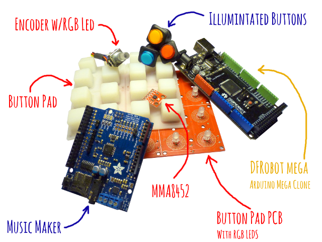
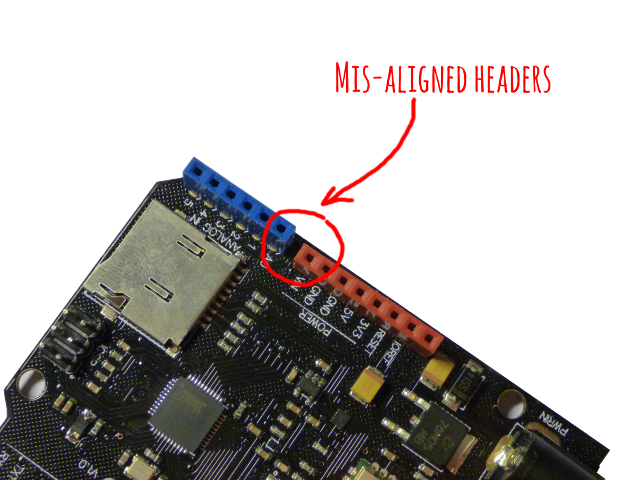
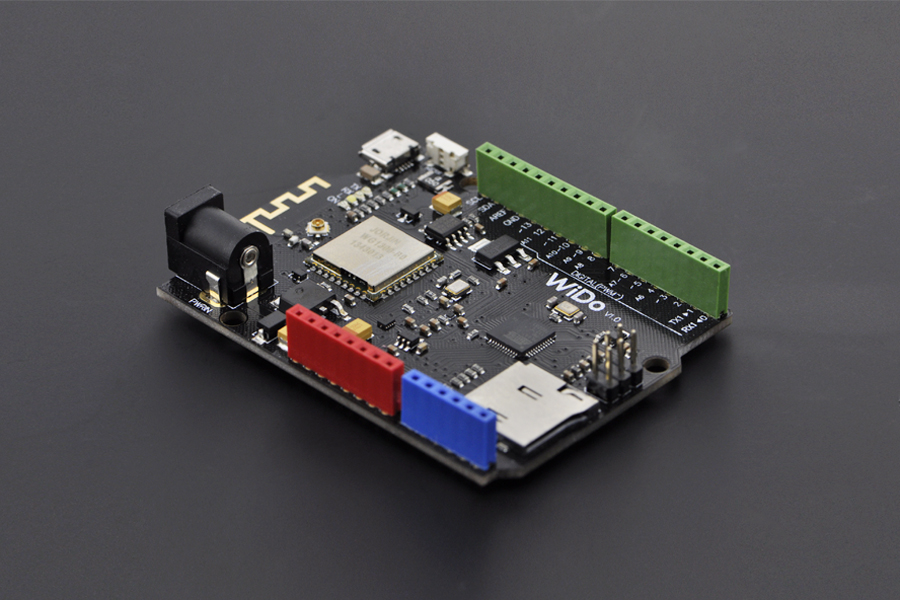
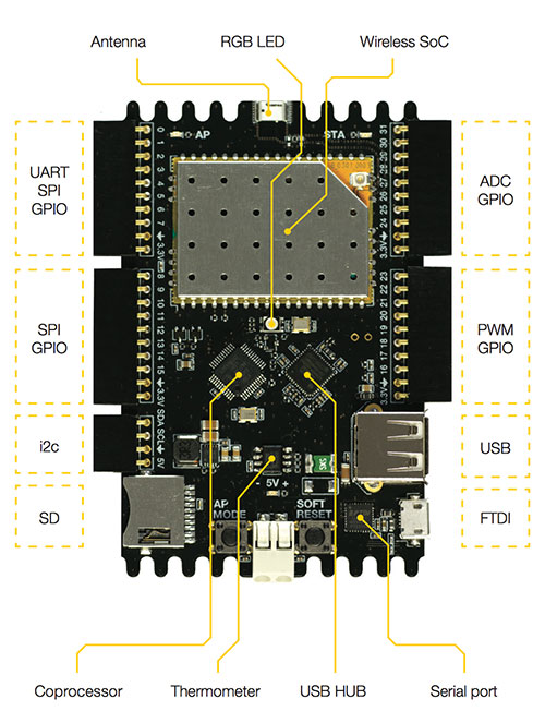
  • an Arduino Mega (here a clone from DF Robot) as the “brain”
  • an Adafruit Music Maker for music & midi player
  • a Sparkfun’s button par and associated PCB (need to get leds separately)
  • some simple illuminated push buttons from found at Adafruit
  • a rotary encoder. Strangely enough, the RGB one I found at Sparkfun is the only which has a threaded shaft with a bolt and then can be mounted on a chassis
  • and last but not least an accellerometer breakout board just for fun also from Sparkfun

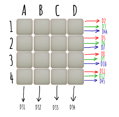
Connecting the button pad

Connecting the Arduino to the button pad is not complex but there are quite a bit of wires between them… I already went through this here. But I changed the pins I used in the first place. Just that I thought it would simplify soldering later on by keeping related pins together as much as possible. Not sure it did simplify though…

final button pad connection

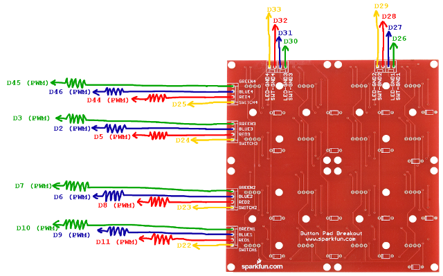
And PWM pins have been chosen precisely because you don’t want to use pins 4 and 13… More on this here.

And last, resistors for the leds are 150Ω, 100Ω and 100Ω for red, green and blue pins.

 Now, the Music Maker

The Adafruit’s Music Maker is based on the VS1053 chip which has 2 main functions : MP3/WAV/OGG… player and MIDI synth. It comes with a handy SD card connector from which it can read files to play. It comes in several flavors :

I chose the latter for two reasons : I liked the idea of having an onboard amp so it would simplifiy cabling and I thought I could stack it onto the Mega. But… as it is using by default PWM pins I desperately need for controlling the leds, I had to re-cable everything to new pins. In addition, I could not stack it anyway because I needed all the space on the Mega proto shield as you’ll see later on.

So, in the end, if I had to do it again, I would probably get the breakout board (smaller, much smaller) and the 3W amp separately.

Here are the connections

music maker connection

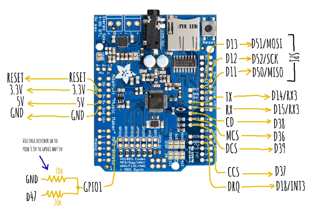
Schematic based on Adafruit’s Music Maker catalog product photo

Note the little voltage divider to feed GPIO 1 on the VS1052 : the VS is a 3.3V device so feeding directly with Arduino’s 5V may (will) damage it.

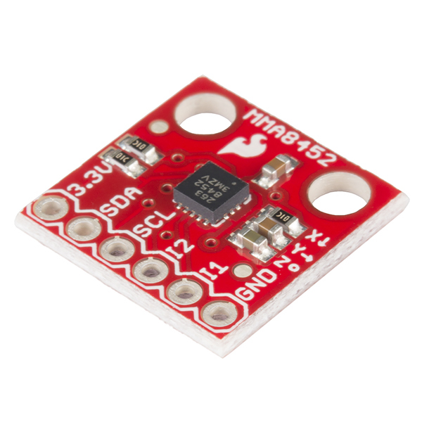
 Then the accellerometer

I choose a cheap 3-axis, I2C capable accellerometer breakout : the Sparkfun’s MMA8452 breakout board.

It has some nice features and can make use of 2 interrupts… but I only have one available… So the other one won’t be connected for now. My first version of arduino code won’t make use of any of it for now. So it does not matter. I did connect one… just in case I have an idea on how I could use it !

mma8452

Schematic based on Sparkfun’s catalog product photo

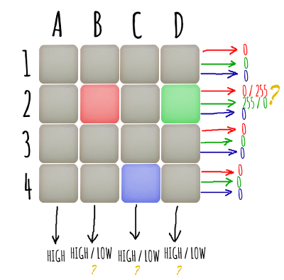
Let’s continue with the encoder

The Sparkfun’s encoder is a bit tricky because documentation is not quite clear but in the end… it works !

encoder connection

Note that it is a common anode RGB led. Setting pins D12, D13 or D14 to 0 means ON and 255 means OFF !

And last, resistors for the leds are 150Ω, 100Ω and 100Ω for red, green and blue pins. Also, pull-down resistor for the switch is 10kΩ

Let’s finish with the buttons

And now the very last thing : the illuminated buttons.

button rear connection

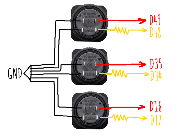
Schematic based on Adafruit’s catalog product photo


Have 3 of them. Quite straight forward… just don’t forget 150Ω led resistors.

Wrap up

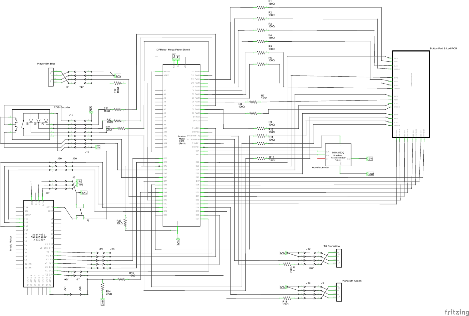
Ok… all parts have been connected one by one, here is the full picture !

schematic 1500

 And what about Arduino code

All is here on GitHub : https://github.com/jsiobj/NoeSoundBox/

What’s next

In next posts, I will sho how I did assemble all that stuff and build a nice enclosure for it.

Noe’s Juke Box | Introduction

Time has gone by since my first post about the sound box… I already wrote a couple of articles about the button pad here, here and here. I finaly came up with something. I did build an autonomous sound box which can act as a piano or act like an MP3 player.

It is based on an Arduino Mega, a Sparkfun’s 4×4 button pad and its associated PCB, anamplified Adafruit’s Music Maker, and a Sparkfun’s MMA8452 triple axis accelerometer breakout board.

There are 3 modes which are demonstrated in the following videos

Player mode

In this mode, you first select a “bank” and then a file to play. Sound / music files are stored and the SD card inserted in the Adafruit’s Music Maker. File is read from the SD and played by the VS1053.

[youtube width=”640″ height=”360″]http://youtu.be/c0TjfgWG8kU[/youtube]


Piano Mode

Here, I use the MIDI mode of the VS1053. You first select a “bank”. Each bank has a specific set of sounds mapped to pad buttons.

[youtube width=”640″ height=”360″]http://youtu.be/_tpAKXBPCoE[/youtube]


Tilt Mode

This mode is quite simple for now : the light is moving using Sparkfun’s MMA8452 triple axis accelerometer data.

[youtube width=”640″ height=”360″]http://youtu.be/PZWHrbSEdJw[/youtube]


What’s next

In following posts, I will go into details of the Sound Box, hardware and software, how to assemble everything…

There is plenty of stuff that could be done : voice or music recorder using microphone input on the music maker, piano record mode, more advanced tilt game, “simon says” game…

WiDo first impressions

I received my WiDos ! Three of them. They were out of stock so I had to wait a few more days after order but they eventually arrived through DHL delivery after one week of patience. I had to pay french taxes in addition the product price. Fair enough : I was warned !WiDo unboxed

The WiDo is an Arduino Leonardo compatible board including a Wifi chip and an SD card reader. It should be noted that some on the pins are used by either the wifi or the SD card : pins D4, D5, D7 and D10 are not available. Also, the wifi chip is using SPI top communicate with the microcontroller.

The Jorjin WG1300 seems to be based on the TI CC3000 chip. So it work with the Adafruit CC3000 library. There is also a WiDo fork for the library but it seems there is no change to the library itself. Only examples are updated (changing IRQ pin from 3 to 7) or created (Xively…)

I stuck to the the Adafruit original. I just loaded the buildtest example, changed IRQ pin, set my Wifi SID and WPA password… and it worked like a charm !

The only problem I have with one on the board is the mis-alignment of some headers.WiDo mis aligned headersIt is not preventing the board to work but you can’t use shields as they won’t fit. I may try to re-solder the header.

So, at around 25€, the WiDo is a great replacement for an Arduino + Wifi shield which costs around 70€ ! And it works just like the Adafruit CC3000 Wifi shield.

The next step is to port the Wifridge on WiDo.

By the way, official documentation is here.


WiDo : a WiFi connected arduino

After presenting WeIO, here is WiDo from DFRobot, yet another Open Source IoT node.

wido

Image from http://www.dfrobot.com

It is basically an Arduino Leonardo which includes a WG1300 WiFi chip. Apparently, this can be used with Adafruit’s CC3000 Arduino library which should make it quite straightforward to use.

What’s the difference between an Arduino + a CC3000 shield then ? The price ! At less that $30, it makes a quite cheap IoT plateform !

Ordered some… (DHL shipping is free until the end of september) but no more in stock. So I don’t know when I will receive them 🙁


WeIO : a new IoT plaform

Back in june, I went to the Maker Faire which took place in Paris.

I saw for the first time a new little but powerfull platform which was under development : the WeIO. It looked like quite promising.

weioImage

Image from http://www.we-io.net/


Creators of this new “Web of Things platform” just launch a crowdfunding campain on INDIEGOGO. Their goal was to reach $10.000… After 2 days, they reached… $9.568 ! No more early bird offer but you can still support them and pre-order this new gizmo ! I just did !

Can’t wait to play with it…

Building a private file sync cloud

I have been looking for the perfect file sync tool for a while now and I wanted to share my experiences. They will hopefully be usefull for someone…

What about Dropbox

Dropbox… For many people, it is one of the best. But for me, there is one thing which is a showstopper : why the hell do you need to reorganize your data to sync with Dropbox ? Why can’t you just say “ok, I would like to sync c:\myshareddata and c:\myprivatedata… and… c:\mymedia\myphotos”.

No… you are REQUIRED to put everything in whatever unique directory or share your all C: drive !

So I found Wuala…

Nice little java GUI, where you can select any existing directory. No need to move your files around. You can sync multiple computers. Wuala provide both sync and backup features, file versionning… In addition, It is base in Swisszerland so if you are allergic to store your private data in the US, it is a nice solution.

A bit expensive though and if you get an issue… don’t ask for help ! I did get a memory leak on Windows 8. And after I sent an email to the support, they did send me immediately a small patch… which did not solve the problem. Without looking further (they did not ask for any log files, diag informations whatsoever) they just said “Ok, it does not work, we’ll reimbourse you”…

Ok… that could mean one thing from my point of view : they really don’t give a sh… about their customer (and can afford reimboursing them) because the service will not last long…

And no client for my NAS…

I’ll eventually gave up, get my money back, and start looking for a new solution.

A quite original solution : “lend” you free disk space

ON my Synology NAS, I also found another Cloud Sync tool : Symform. It is a a real “Cloud” storage in that it is storing data on many customer PCs : you actually “lending” your own disk space for storing other customer data and get cloud storage space in return. You actually give twice as much as you get but I find this a very good idea.

I tried it on my PC for a while and it worked quite well. I then decided to install it on my NAS but, I don’t know why, upload time became soooooo looooonnnnng I just gave up. I think I will try this again when I get FTTH connection.

What about not using a public cloud service

I got a nice Synlogy NAS (a DS411) and I wondered : “Why can’t I make my own sync cloud ?”.

The first I tried was Synology own Cloud solution : Sync Station. But it is not build for high volumes. When I started the sync, 10 Gb of data became… 20 Gb because of the way the tool is backuping old version… even on first sync ! Silly… But I must admit I tried a while ago and they may have made some progress.

And then came Bittorrent Sync…

I discovered BT Sync a while ago as they were still at version 1.3. A very nice sync tools making used of Bittorrent protocol and allowing sync of multiple hosts in a quite simple way.

I did sync all my photos and music between my home PC and my NAS and it worked quite well. I also sync’ed my personnal file between my home PC, my NAS and my laptop. And finally, I convinced on of my coworkers to install it so we can easily share files.

Worked for a while… then, you don’t know while, it just get stuck at some point. You remove a partially sync file (you need to enable debugging to identify the file) and then, it restart.

I had a few corrupted file also. I was able to get a backup from the BT Sync trash… on another machine. BT Sync team, if you read this : why, when I delete a file locally, it does not got to local trash but only to remote trash ?

1.4 version, which is quite recent, brought a much nicer UI. You can easily share files…

2014-09-13 00_06_46-BitTorrent Sync

And I was hoping a bit more reliabilty. Alas… Still get sync hanging for no apparent reason, but in addition, BT Sync tends to lock the files which are open in MS Office… which then you can’t save !

And right now, while I am writing this post, my NAS and home PC are both saying “OK, everything is now in sync” but my laptop is still pretending there is more than 1 Gb of files to sync…

How can you trust this…

Will the next solution be the good one

And while I was looking for some tips and trick about BT Sync and find solutions to my problems, I found a new sync tool, thank to this post : SyncThings. It seems that since Korben published this, they have made some progress and it looks like quite promising.

2014-09-13 00_12_53-Syncthing _ PCJS

Another important point : it is Open Source.

So I’ll try that and hopefully, it will cover my needs !

Sparkfun’s 4×4 Button & LED Matrix – Part 3 – Playing with the pad

In previous posts, we saw how to assemble the pad and how to connect it to an arduino MEGA and use a very simple program to switch led on and of using the keypad. Now, this is getting a bit more complex as we will :

  • detect simultaneous key press (up to 10)
  • use key status (PRESSED, HOLD, RELEASED and IDLE) to do stuff
  • lights up multiple leds with different colors

What the program will do

On startup, it will lights up every led in red, green, blue and white successively. It is just a test to verify that the 3 RGB pins of all leds are properly wired to the arduino.

Then, it will lights up all leds at once with random colors.

Then, when using a key :

  • If the led off
    • When key is pressed, led will be switched on with a random color
    • if the key is not held long enough, the led will be switched off when the key is released
    • if the key is held long enough, when it is released, led will stay on
  • If the led is on
    • When key is pressed, led color will change
    • if the key is not held long enough, the led will be switched off when the key is released
    • if the key is held long enough, when it is released, led will stay on with the new color

[youtube width=”640″ height=”360″]http://youtu.be/4QhD3rGYXbE[/youtube]

Not really usefull… but it should show how all this works and get you started the the pad !

Detecting multiple key press

No magic here : I simply used Keypad library from Arduino’s playground. I used the MultiKey example provided with the library to get my code working.

How to get all leds switched on with different colors

4×4 led matrix (more specifically Sparkfun’s 4×4 led matrix) requires :

  • 3 x 4 PMW pins that is 3 pins per row of 4 leds (against 3×16=48 PWM pins if each led was to be controlled individually)
  • 4 ground pins (against 16 pins…)

(See here for some details on RGB leds and have a look here for PWM pins.)

Let say PWM pins are rows and GND pins are columns

4x4 button pad sample with pins

If you want to make the B2 led red, then you just set D5 to 255 and D32 to LOW.

4x4 button pad sample 1 red

But, although requiring much less pins, matrix have some drawbacks :  what if you want to ligh up B2 and C3 and also B2 to be red and D2 to be green ? All at the same time ?

4x4 button pad sample 3 red green blue

All 4 leds in a row share the very same 3 “colors” pins and all leds in a column share the very same ground. It is not directly possible to have 2 differents colors for 2 leds on the same row. And it is not possible to switch on only 2 leds which are not on the same columns.

One way is to switch all leds on and off successively. Or better (more efficient),

  1. set colors on all the rows for the 1st column
  2. switch column on
  3. wait “leds on” for a little while (else leds will look quite dimmed)
  4. switch column off
  5. go to the next column (back to 1)

4x4 button pad sample 4 process

I noticed that waiting for 4ms was giving some fickering. I needed 3ms or less to get a “flicker free” display.  I finally get down to 300μs “led on” period. This is sufficient to get the maximum brightness and definitively get rid of flickering.

Here is a small video showing the same led pattern as above, starting with a 500ms period down to 2ms.

[youtube width=”640″ height=”360″]http://youtu.be/E1xLP7nZ4Cw[/youtube]

PWM trick

I did connect the leds a bit differently than in the previous article. That is, I swapped  pins
4 & 13 respectively with pin 44 & 45. Why didn’t I used pin 4 & 13 and 44 & 45 instead ?

Because I needed to increase PWM frequency to make the matrix works. To do this, you need to change timers config. Pins 4 and 13 use timer 0. But… as timer 0 is used by Arduino’s core timing functions, you don’t want to mess with it. Do you ?

But why the heck did I want to change PWM frequency ! Because it too “slow” by default. On an Arduino MEGA, default frequencies are :

  • 976.56 Hz for pin 4 & 13
  • 490.20 Hz for all other PWM pins

As stated above, I won’t be using pins 4 & 13. So frequency fo pins I use is a bit less that 500 Hz, that is, a period is a bit higher that 2ms. This is veeeeeeeery loooong… waaaaaay too long because I wait for 300μs and can only “wait” up for 3ms max anyway (not to get flickering). So, even for 3ms, that is around 1 and a half PWM period. This is not enough to get a stable color.

So I increased PWM frequency to the maximum, i.e. 31372.55 Hz. That makes a PWM period of ~32μs which is much smaller of even the smallest 300μs “led on” period.

More on PWM :

  • http://arduino.cc/en/Tutorial/SecretsOfArduinoPWM
  • http://playground.arduino.cc/Main/TimerPWMCheatsheet
  • http://playground.arduino.cc/Code/PwmFrequency
  • http://letsmakerobots.com/node/40136
  • http://letsmakerobots.com/content/arduino-101-timers-and-interrupts

And now the code

I finally built up my very first library based on some OO code. It is to be used with an Arduino Mega and the Sparkfun’s 4×4 button pad.

As this is my first library, it may (does) require improvements… I know. But I hope it will at least get you started !

All the code is here on GitHub.