In this post, I will give the details of the WiFridge hardware : how to connect the probes to the Arduino. It follows the post here.
The hardware
Here is the bill of material :
- 1 AM2302 Humidity & temperature sensor
- 2 DS12B20 1-wire waterproof temperature sensor
- 3 3mm LEDs (green, yellow, red)
- 3 1kΩ resistor
- 1 10kΩ resistor
- 1 4.7Ω resistor
- 1 Arduino Wireless shield
- 1 RN-XV Wifly module
- some solderless breadboard
- a bunch of wires
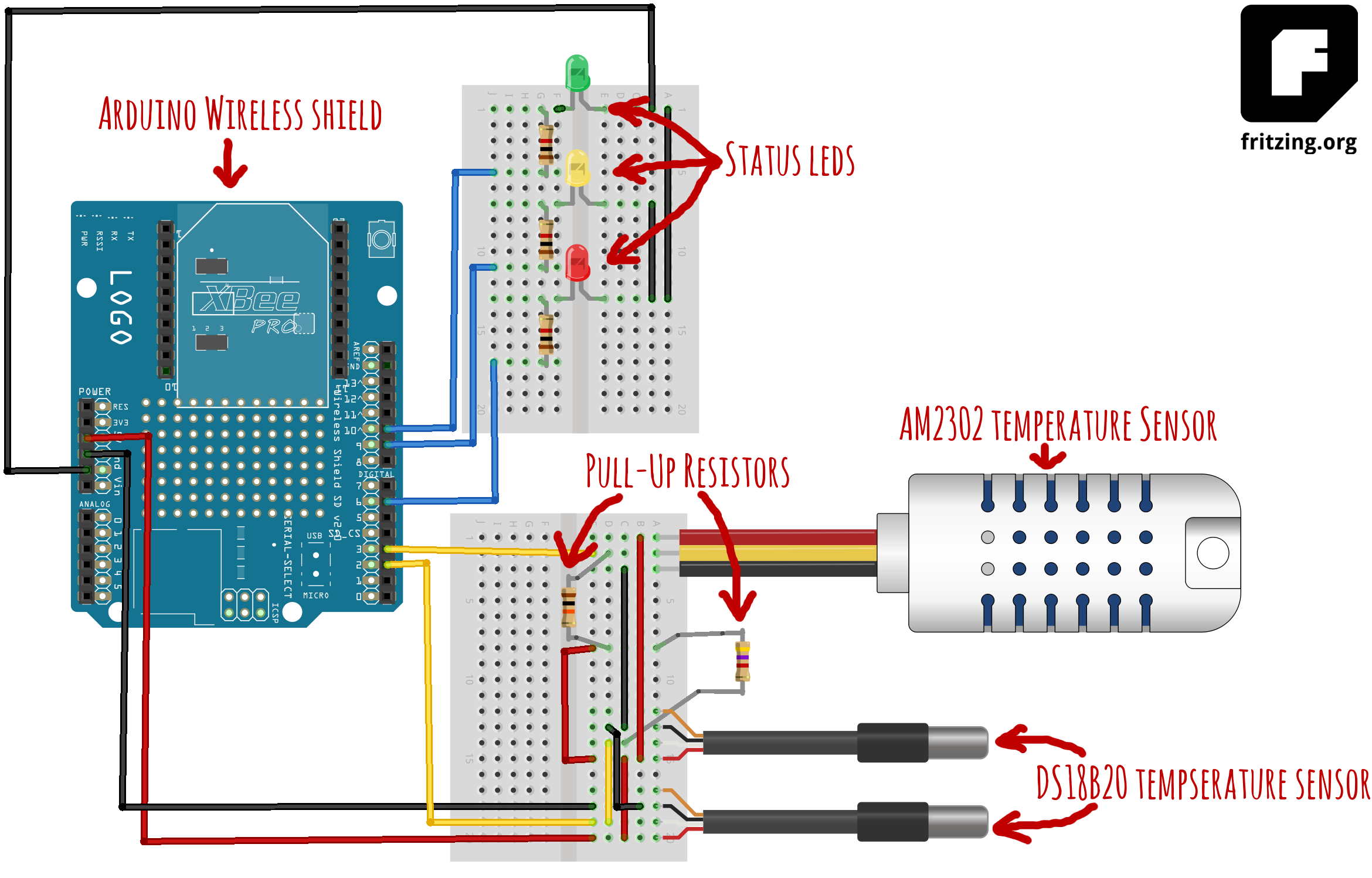
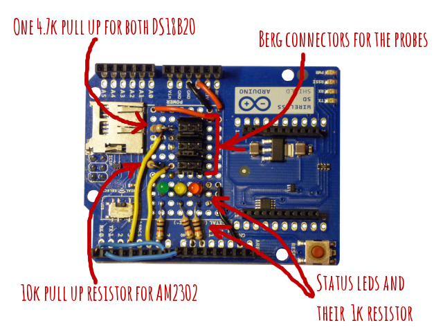
It is connected as describe on the previous figure (created mostly with Fritzing.)
- AM2302 : data connected on digital input 3 for kitchen temperature and humidity connected to a 10kΩ pull-up resistor
- both DS18B20 : data on digital input 2 for fridge and freezer temperature, connected to a 4.7Ω pull-up resistor
- status leds on digital inputs 6, 9 and 10 (optionnal though, just here for displaying status when operating) through 1kΩ resistors.
The 3 sensors are also connected to ground and +5V through their corresponding wire.
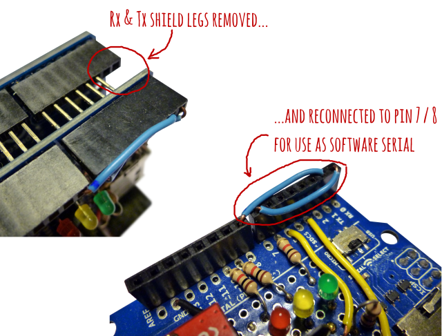
Also, to simplify debugging, I decided to connect WiFly UART to a software serial port on the Arduino so that the hardware serial is free for programming and debugging. I simply cut off the Rx and Tx legs on the shield and reconnected them to digital pin 7 & 8. But it is possible to only bend the legs so you can revert the process.
That’s it for the hardware. In a coming post, I will describe the software part.