In previous posts, we saw how to assemble the pad and how to connect it to an arduino MEGA and use a very simple program to switch led on and of using the keypad. Now, this is getting a bit more complex as we will :
- detect simultaneous key press (up to 10)
- use key status (PRESSED, HOLD, RELEASED and IDLE) to do stuff
- lights up multiple leds with different colors
What the program will do
On startup, it will lights up every led in red, green, blue and white successively. It is just a test to verify that the 3 RGB pins of all leds are properly wired to the arduino.
Then, it will lights up all leds at once with random colors.
Then, when using a key :
- If the led off
- When key is pressed, led will be switched on with a random color
- if the key is not held long enough, the led will be switched off when the key is released
- if the key is held long enough, when it is released, led will stay on
- If the led is on
- When key is pressed, led color will change
- if the key is not held long enough, the led will be switched off when the key is released
- if the key is held long enough, when it is released, led will stay on with the new color
[youtube width=”640″ height=”360″]http://youtu.be/4QhD3rGYXbE[/youtube]
Not really usefull… but it should show how all this works and get you started the the pad !
Detecting multiple key press
No magic here : I simply used Keypad library from Arduino’s playground. I used the MultiKey example provided with the library to get my code working.
How to get all leds switched on with different colors
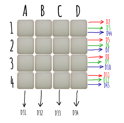
4×4 led matrix (more specifically Sparkfun’s 4×4 led matrix) requires :
- 3 x 4 PMW pins that is 3 pins per row of 4 leds (against 3×16=48 PWM pins if each led was to be controlled individually)
- 4 ground pins (against 16 pins…)
(See here for some details on RGB leds and have a look here for PWM pins.)
Let say PWM pins are rows and GND pins are columns
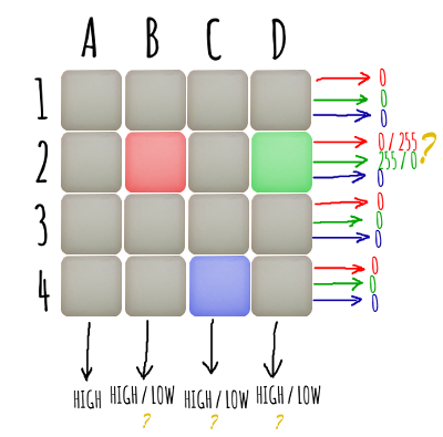
If you want to make the B2 led red, then you just set D5 to 255 and D32 to LOW.
But, although requiring much less pins, matrix have some drawbacks : what if you want to ligh up B2 and C3 and also B2 to be red and D2 to be green ? All at the same time ?
All 4 leds in a row share the very same 3 “colors” pins and all leds in a column share the very same ground. It is not directly possible to have 2 differents colors for 2 leds on the same row. And it is not possible to switch on only 2 leds which are not on the same columns.
One way is to switch all leds on and off successively. Or better (more efficient),
- set colors on all the rows for the 1st column
- switch column on
- wait “leds on” for a little while (else leds will look quite dimmed)
- switch column off
- go to the next column (back to 1)

I noticed that waiting for 4ms was giving some fickering. I needed 3ms or less to get a “flicker free” display. I finally get down to 300μs “led on” period. This is sufficient to get the maximum brightness and definitively get rid of flickering.
Here is a small video showing the same led pattern as above, starting with a 500ms period down to 2ms.
[youtube width=”640″ height=”360″]http://youtu.be/E1xLP7nZ4Cw[/youtube]
PWM trick
I did connect the leds a bit differently than in the previous article. That is, I swapped pins
4 & 13 respectively with pin 44 & 45. Why didn’t I used pin 4 & 13 and 44 & 45 instead ?
Because I needed to increase PWM frequency to make the matrix works. To do this, you need to change timers config. Pins 4 and 13 use timer 0. But… as timer 0 is used by Arduino’s core timing functions, you don’t want to mess with it. Do you ?
But why the heck did I want to change PWM frequency ! Because it too “slow” by default. On an Arduino MEGA, default frequencies are :
- 976.56 Hz for pin 4 & 13
- 490.20 Hz for all other PWM pins
As stated above, I won’t be using pins 4 & 13. So frequency fo pins I use is a bit less that 500 Hz, that is, a period is a bit higher that 2ms. This is veeeeeeeery loooong… waaaaaay too long because I wait for 300μs and can only “wait” up for 3ms max anyway (not to get flickering). So, even for 3ms, that is around 1 and a half PWM period. This is not enough to get a stable color.
So I increased PWM frequency to the maximum, i.e. 31372.55 Hz. That makes a PWM period of ~32μs which is much smaller of even the smallest 300μs “led on” period.
More on PWM :
- http://arduino.cc/en/Tutorial/SecretsOfArduinoPWM
- http://playground.arduino.cc/Main/TimerPWMCheatsheet
- http://playground.arduino.cc/Code/PwmFrequency
- http://letsmakerobots.com/node/40136
- http://letsmakerobots.com/content/arduino-101-timers-and-interrupts
And now the code
I finally built up my very first library based on some OO code. It is to be used with an Arduino Mega and the Sparkfun’s 4×4 button pad.
As this is my first library, it may (does) require improvements… I know. But I hope it will at least get you started !
All the code is here on GitHub.


