Introduction
There are quite a few project out there using Sparkfun’s Button Pad 4×4 – LED Compatible and associated Button Pad 4×4 – Breakout PCB. But most of the time there are either using monochrome leds and a shift register to drive the leds or just using a 2×2 matrix. So I decided to write my own build guide with RGB leds and an Arduino MEGA.
This is the first part of this building guide. In this part, I’ll list parts I used and show how I soldered everything together. In next part, I will describe connection of the pad to an Arduino MEGA and all necessary code to test it and make some fun things.
The parts
You’ll need :
- 1 Sparkfun’s Button Pad 4×4 – LED Compatible
- 1 Sparkfun’s Button Pad 4×4 – Breakout PCB
- 16 5mm diffused common cathod RGB leds
- 16 1N4148 diodes
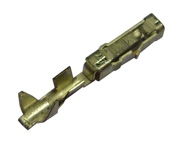
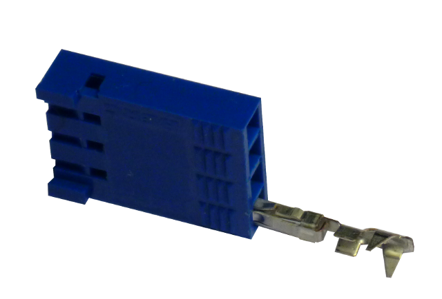
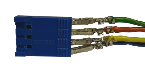
- 6 BERG 4P male connectors and 6 BERG 4P female connectors and
- few meters of 4 wire ribbon cable
That’ll be it for the soldering. But in the next parts, I will also be using
- 1 Arduino Mega
- 12 150Ω resistors
- a few jumper wires
- one big breadboard (or 3 small ones)
I bought my parts mainly from 2 french retaillers in or near Paris : Lextronic as they are a Sparkfun’s reseller and Saint-Quentin Radio for basic electronic pars (such as resistors, diodes, cable…) But you can find almost everything at Sparkfun’s or your prefered shop !
The soldering
Lets have a look at the PCB first. On the “bottom” side, we will solder the 1N4148 diodes and the BERG connectors. On the “top” side, where the botton pad will rest, we will solder the RGB leds.
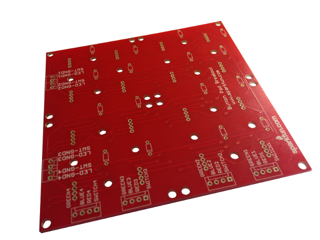
Bottom side : where diodes and connectors go
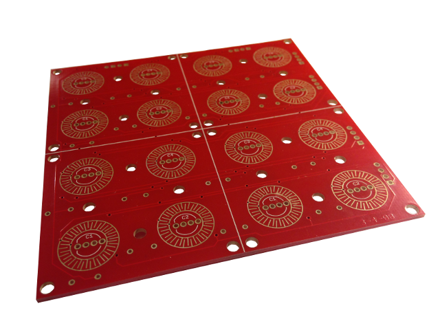
Top side : where RGB leds and rubber buttons pad (below) goes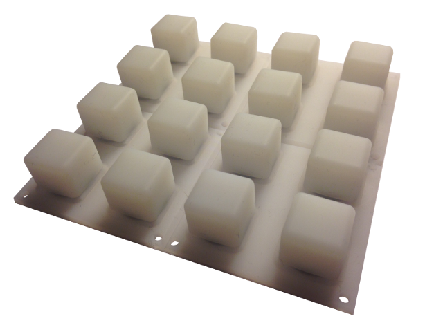
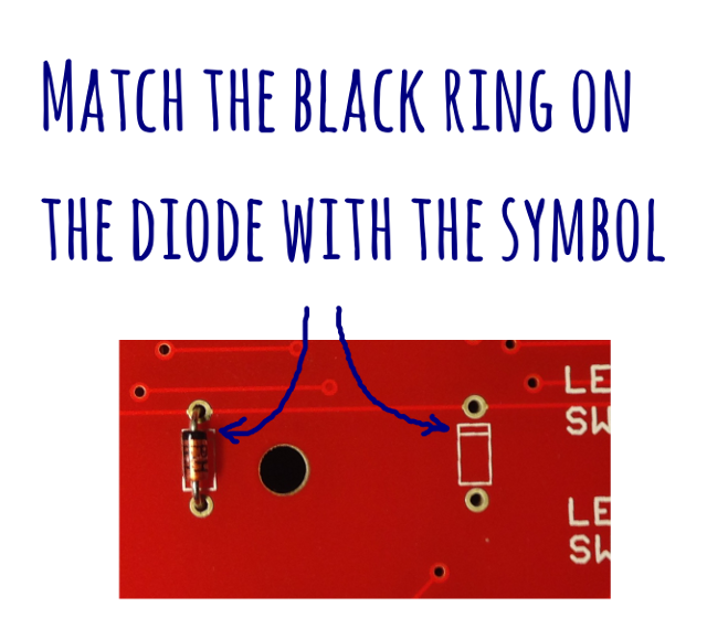
1N4148 diodes : the easy part
Not much to say really… Just bend the legs, insert the 16 diodes required in the proper holes and solder. Just one thing to take care of : the orientation on the diode !
Then, solder the diodes on the top side, taking care of not putting to much solder as you will need to trim the legs as close as possible from the PCB (I used a specific plier / cutter like this one) so it won’t get in the way of the rubber buttons pad.
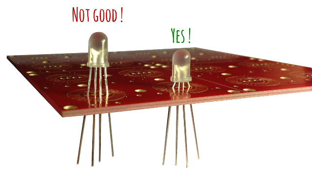
RGB leds
Not much more complex. But leds I used have legs a bit closer from one another that the holes are. So you need to bend the legs before trying to insert them. If you don’t, you won’t be able to push them enough.

Then solder the legs of the leds !
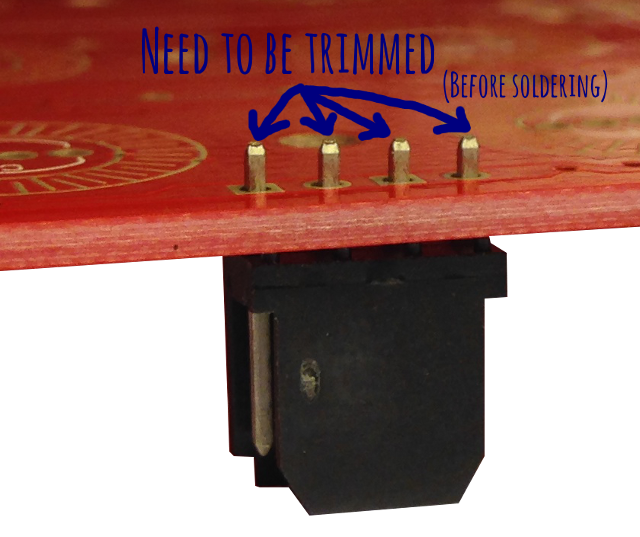
The BERG connectors
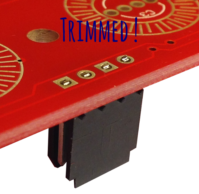
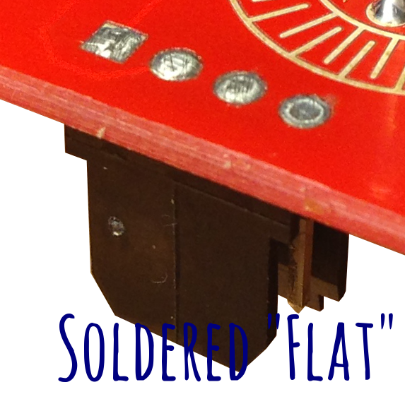
Again, one tricky part is that you need to keep soldering on the top side as “flat” as possible, else, rubber pad won’t lay down properly on the PCB.
What I did is “trim” the BERG connector BEFORE soldering so it flush with the PCB. Doing it after is much more difficult and you may (will) damage the solder joint. Whan soldering, make sure you heat the BERG pins with the iron so that you build a solid solder joint.
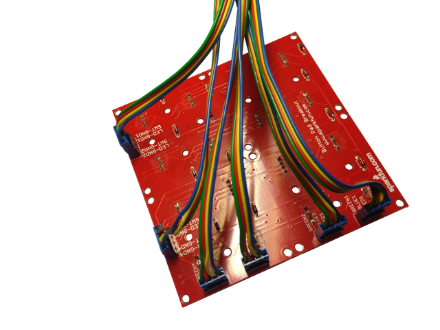
Cabling
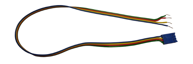
Ok, now we need some wires to connect the PCB to an arduino. I used a 4 wire ribbon cable. On one side, I just tin-plated the wires so that they can be easily used with a solderless breadboard. On the other side, I used the female BERG connectors.

And in the end…
… we get a fully assembled button pad !